The common fuse is a very handy little electrical safety device that is designed to fail in the event that the appliance they are attached to tries to draw too much power.
The most basic of fuses, the plug fuse or cartridge fuse is simply just a piece of wire (thickness of wire depends on amperage of fuse) between two conductors. The incoming current comes in at one end, passes through the wire and out of the other end and on to the appliance.
If the current being drawn by the appliance is too great, the wire heats up and burns through and cuts the power, saving the appliance and also you.
In this guide we take a look at how to test a fuse to ensure it’s not blown and in full working condition. You will learn how to test a fuse with a multimeter and also using a battery and bulb
Tools and Products Needed for Testing Fuses
In order to test a fuse correctly you will need the following tools and products. Which ones you require will depend on the testing method you are using:
- Car battery
- Standard car bulb
- Cartridge fuse
- Tape
- Multimeter
- Length of wire
- Wire strippers
How to Test Cartridge Fuses or Plug Fuses
If you have just bought a pack of fuses from a shop you can be almost a 100% certain that they will all be working.
However if it’s late on a Sunday night and all the shops are closed and the fuse has just gone in the iron and you need to iron your best shirt for your job interview first thing Monday morning then those old fuses knocking around in the bottom of the drawer are your only choice.
However before simply sticking it in the plug it’s a good idea to test it first to make sure it is fully functional. Here follows a few methods for doing so.
Step 1 – Visually Inspect the Fuse
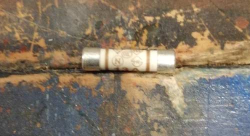
The first and most obvious check to make is a visual one. Carefully look at the fuse and check for any obvious damage including any crushed areas of the body or ends that may result in them not fitting correctly.
If any damage is evident throw the fuse away and do not be tempted to use it.
The final check is to look for any corrosion or deposits on the contact ends of the fuse. Again if any is evident then the fuse should not be used.
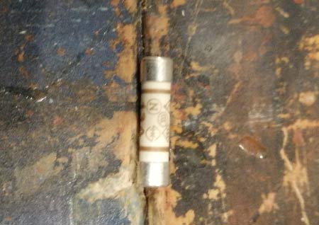
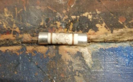
Visually inspecting a cartridge fuse
Step 2 – Testing a Fuse Using a Battery and Light Bulb
If after visual inspection the fuse is free from damage and any corrosion etc. before actually using it in a live appliance it’s a great idea to also actually test it to make sure it’s fully working.
One of the simplest methods of doing so is to use a battery and light bulb. Here follows some steps on how to do so:
- Cut a length or electrical wire to around 300mm in length and strip both ends. Any wire should be fine to use as long as it’s capable of carrying a current. In this instance we didn’t have any to hand, only an old length of cable with a crocodile clip on it, which sufficed as we could clip the bulb in the clip. Strip off around 20mm at both ends of wire
- Next find a suitable bulb. As we are testing with a 12V battery the best bulb to use is a car brake light bulb
- Using some tape (Seloptape or masking tape), tape one end of the wire to the silver body of the bulb, below the actual glass
- Next, hold the other stripped end of the wire at one contact end of the fuse
- Finally, position the bulb over the plus (+) terminal of the battery and lower it so that the contact point on the base of the bulb is touching it. Taking the other end of the wire, position the end of the fuse that is not fixed to the stripped cable over the battery negative terminal (-) and lower it so that it touches
- If the fuse is in good condition and fully working, when it touches the negative terminal it will complete the circuit and the bulb will light up. However if it is damaged it will not complete the circuit and due to this the bulb won’t light up
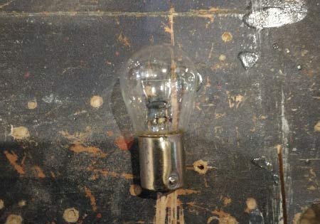
Car bulb to use for testing
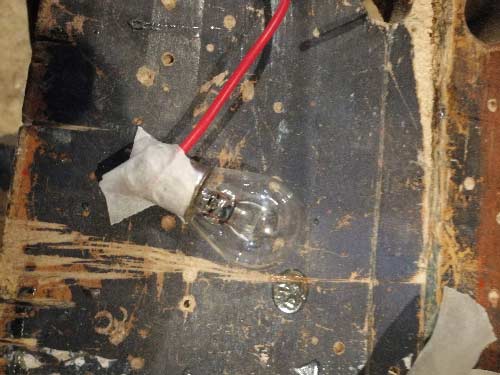
Wire taped to bulb
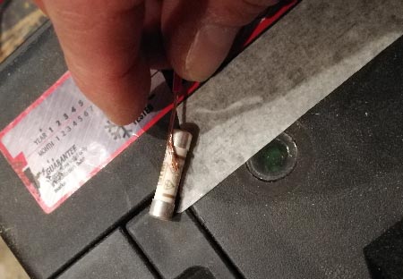
End of wire held on to end of fuse
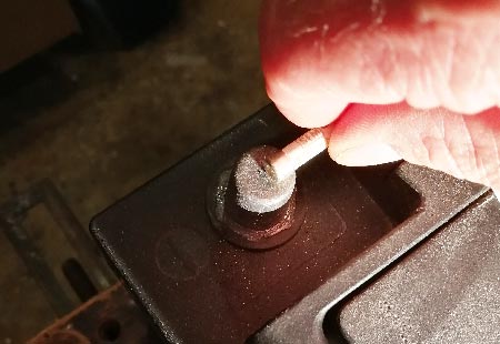
Fuse positioned over battery negative terminal
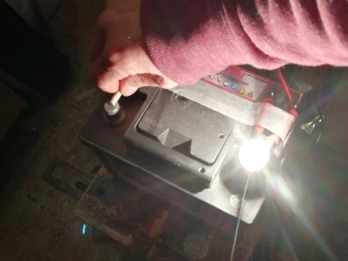
Circuit completed using a working fuse will cause bulb to light up
Although this is a rather crude method of testing a cartridge fuse to ensure it is working it is indeed very effective and will tell you in a short amount of time whether or not your fuse is defective.
Step 3 – Testing a Fuse With a Multimeter
The above method is one to use if you don’t have any other means of testing a bulb, however if you have a multimeter knocking around then you can certainly use this to test any fuses quickly and easily.
There are 2 different methods for testing a fuse using a multimeter; Using the meters continuity test feature or if it doesn’t have one using the ohms setting.
Using the Continuity Test
If your meter has a continuity test feature this is the option to go for, but be aware that not all multimeter’s have them. To identify if your meter has this particular feature it should have a symbol similar to the one below:
Continuity test symbol on multimeter
You may also see an additional symbol next to the above one that looks like 4 or 5 curved waves (e.g. a speaker symbol). This indicates that your meter also has an audible test e.g. a buzzer.
In essence a continuity test indicates that there is a fully closed and complete circuit present that allows current to flow indicating continuity of the circuit.
- If you are removing a fuse form a circuit, appliance etc. for testing, ensure all power is first isolated e.g. fully turned off!
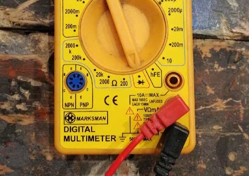
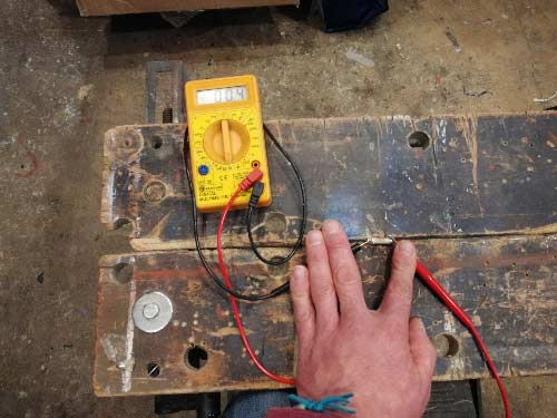
- First, turn the meter on and set it to the continuity setting. Ensure that the red probe cable is connected to the ohms socket (VΩmA) and the black cable is connected to the Comm socket.
- Touch the two probes of the meter together to test that the meter is working correctly. The read out on the digital screen or analogue needle should show a low reading or the buzzer should sound to indicate the circuit is closed
- Place the fuse to be tested down on a non-conductive surface such as a work bench or worktop
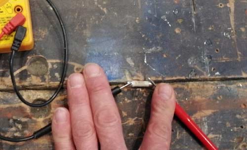
- Position each of the multimeter probes at either end of the conductor points of the fuse
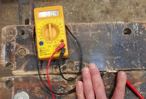
- If your multimeter has a buzzer it should sound indicating the circuit is closed and working but if not check the screen or needle reading, it should be low indicating little to no resistance
Meter turned on and set to continuity test
Testing multimeter working by touching probes together
Fuse positioned on non-conductive surface for testing
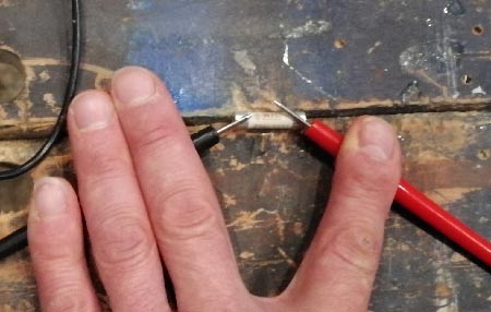
Probes position on fuse
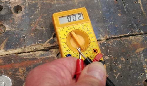
Digital meter showing very little resistance when testing fuse indicating it’s fully working
Using the Ohms Setting
If however your meter doesn’t feature a specific continuity test it should be possible to still use it to test using the ohms setting. Again, this will simply test the circuit for resistance in ohms where a low resistance indicates the circuit is closed and fully working and a high rate of resistance indicating that the circuit is open and not working.
- If you have to remove the fuse before testing, ensure the circuit, appliance etc. is fully isolated before attempting to remove the fuse itself!
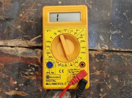
- Turn on the multimeter and set it to the lowest ohm setting available. Most meters will have 5 settings ranging from 2000k down to 200. Also ensure that the red cable is connected to the ohms socket (VΩmA) and the black cable is connected to the Comm socket
- Next, check the meter is fully working by touching the two probes together. The reading should be very low indicating little to no resistance
- Lay the fuse you are going to test down on a non-conductive surface such as worktop or work bench
- Touch each of the probes at each end of the fuse and hold them in place ensuring they retain a good contact
- If you have a meter with audible feature you should hear a short buzz to indicate all is working but if not check the reading. As with the above it should be very low indicating little to no resistance in the circuit
Ohm setting set on front of multimeter
Fuse laid on non-conductive surface for testing
Probes held at each end of fuse for testing
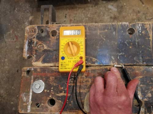
Low reading from multimeter ohm test indicating low resiatance and a working circuit
How to Test a Rewirable Fuses
Depending on the age of your property you may or may not have ever seen a rewirable fuse. This type of fuse was the fuse used in older type fuse boxes before the days of consumer units and MCB’s.
In actuality they are very similar to the small cartridge-type fuses that we have mentioned above, only a little bigger and in this case the fuse wire is replaceable.
To check a rewirable fuse to ensure it hasn’t blown is a fairly simple task:
- First, turn off the power to the circuit for the fuse you are testing. You may be able to do this for the individual circuit or you may have to isolate the power to the entire fuse box as the main on/off switch
- Remove the fuse by gently pulling it out of the socket on the fuse board
- Lay the fuse down on a flat surface so that the sockets are facing upwards
- To check that the fuse hasn’t blown check the small inspection window between the two sockets and you should see that the fuse wire is still intact. If it isn’t then the fuse has blown and the wire needs replacing
- Replacing the wire if needed is fairly easy. Using a small screwdriver, loosen each screw on each socket and then remove the old wire. Select and cut a length of exactly the same wire (has to be exactly the same!!) and slot it through the fuse body. Wrap each end of the wire around each screw keeping the wire fairly tight and tighten each screw fully. Replace the fuse, turn on the circuit and check all is well
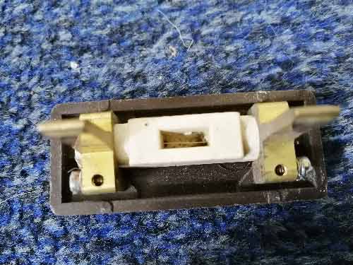
Rewirable fuse ready for inspection testing
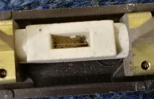
Checking fuse wire in rewirable fuse
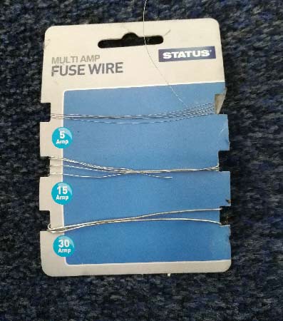
Replacement fuse wire for rewirable fuses
Rewirable fuses are now pretty much obsolete and it’s rare that you will find a rewirable fuse box still in use in a property as it’s much more preferable to get them changed over to a more modern consumer unit.
Testing Consumer Unit Fuses – RCD’s, MCB’s etc.
On the subject of consumer units, although not exactly, the MCB’s, RCD’s etc. in a consumer unit are technically fuses also although they don’t quite work in the same way.
With a fuse, if too much current is passed or pulled through a given circuit, the fuse wire heats up, fractures and cuts the power to the circuit. With an MCB if an overload is detected the MCB trips and cuts power to the circuit.
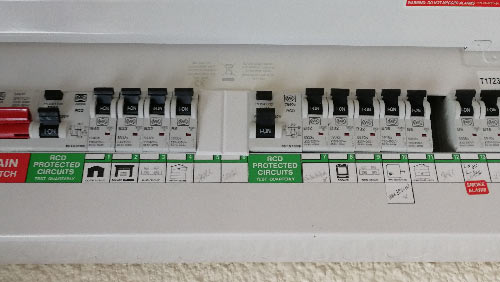
MCB’s present in a modern consumer unit
As we have discussed above, once a fuse has blown it then either needs to be fully replaced or the wire replaced in the case of rewirable fuses, but with an MCB or RCD you simply flick the switch back on to reset the circuit and turn everything back on.
This presents a much simpler and easier to use system than those of the past with testing a given circuit simply just a case of lifting the lid of your consumer unit and visually inspecting which MCB’s RCD’s have indeed tripped.
Testing fuses of any kind whether they are simple cartridge fuses, rewirable fuses or even an MCB is a fairly simple job but one point to be aware of is that it’s essential that you isolate the cause of the tripped or blown fuse before using the circuit again.
The best way to isolate the actual cause of a tripping MCB or RCD is to unplug every appliance or object on the circuit and then turn the circuit back on. If it still trips with nothing plugged into it then this is the sign of a serious issue and you should call a professional electrician immediately.
If it doesn’t trip then you will need to systematically plug in and turn on each appliance one at a time until you find the object that causes the trip. Once you have found the offending item it will then need to be tested professionally and repaired before it can be used again or indeed replaced if it is beyond repair.
The fact that something (appliance cable, socket etc.) is causing a blowing or tripping issue is a sure sign that it’s faulty and indeed dangerous so don’t ignore it, get the professionals in and get it sorted!