In the majority of homes, cold water enters the building via a rising main. This water is then directed to one or two of the downstairs taps where it is at full mains pressure. This direction is done using a T fitting with the other outlet of the T taking the water to a cold water tank in the loft. From there it is distributed around the house. (click here for diagram of water systems)
Regulations state that the cold water tank and indeed the cistern must have a close fitting lid to ensure that the water in these tanks or cisterns cannot be contaminated accidentally. The lid must not however, make the cold water tank or cistern airtight.
Rising Main
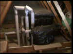
Cold water tank and cistern in roof space
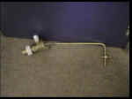
The water going into the storage tank is controlled by a float valve. The valve operates using a plastic (sometimes metal) ball which floats on the surface of the water, this is attached to an arm which is in turn attached to the valve mechanism. When the float rises, it lifts the arm which closes the valve and stops water entering.
These valves are dealt with in greater detail further on in the project. If anything should go wrong with this valve, overflow pipes are fitted to water tanks and cisterns to allow water to flow out before reaching a level where they could overflow the tank. These overflow pipes are also called warning pipes and the end must be placed where any discharge can be seen clearly. The overflow pipe can be seen clearly in the top left of the picture below.
If an overflow pipe, either from your toilet cistern or from the cold water tank in the loft area is dripping, an adjustment of the height of the ball arm does not cure the problem, the remedy will be to exchange one of the black rubber diaphragms, according to the valve you have, in the pictures and diagrams below. The water must be turned off and the operation is simple. The rubber diaphragms are available at most diy stores and plumbers merchants.
Ball valve in roof
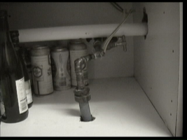
The distribution of cold water to the taps is a direct one interrupted, we suggest, with the insertion of isolation valves at the appropriate points. These valves allow you to turn off the supply to that particular item (basin, sink, cistern etc) without turning off the mains. An isolation valve is shown below
Isolation valve on water pipe
With the more common indirect water supply, the mains pressure going to at least one downstairs tap, can also be tapped into for a washing machine, water softener or dishwasher. All of which need mains pressure to work. An electric shower can also be connected to the mains supply but all of these connections, if needed, must be made after the feed pipe to the first tap.
A cold water pipe will also feed an immersion tank if you have one. This feed will enter the immersion at the bottom, the water will then be heated and as it gets hotter, will rise to the top. The pressure from the cold feed in, will then force the hot water out of the top of the immersion when the hot taps are opened. Water bylaws insist that every pipe and fitting is given maximum protection from freezing by whichever means are appropriate. This generally means that the pipe or fitting should be covered with an insulation material. Smaller pipes are more vulnerable than larger pipes and the insulation should be of a material that does not allow moisture absorption. The minimum thicknesses of insulation required are:
- 15mm pipe: 25mm
- 22-28 mm pipe: 19mm
- 35mm and over pipe: 9mm
The tops and sides of tanks and cisterns in the loft should also be insulated, but no insulation should be placed under the tank to avoid condensation.
Cistern Valves and Valves
There are a few variations on a theme as far as cistern valves are concerned. The valves connected to the mains must be high pressure valves, and the lower pressure fittings need low pressure valves. There are also valves to reduce the noise made when filling a cistern.
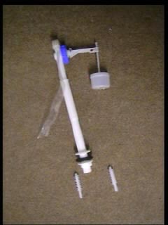
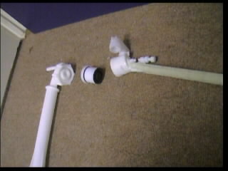
Most loft tanks will have a brass, high pressure valve as in the picture above. The picture below shows exactly how this valve works. The ball is screwed to the adjustable thread on the end of the arm. The arm can be detached from the body of the valve by the ribbed nut which can be seen at the end of the arm in the left hand picture. In the right hand picture you can see the black rubber diaphragm which is pushed against the water inlet by the action of the float rising with the water. This closes the valve.
Ball valve arm
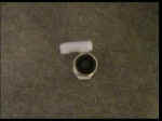
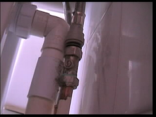
Isolation valve
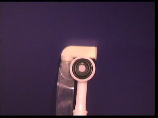
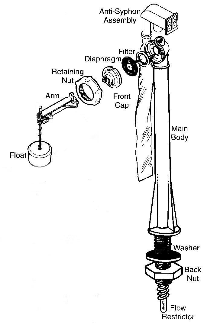
For a quiet operation, the Torbeck valve has been introduced. This one is both high and low pressure, with threaded inserts which can be added to the valve in accordance with the pressure. The size of the float and the smooth operation of the arm, ensure that water hammer does not occur. Torbeck valves have side and bottom entry designs for use in most applications. These valves are used in toilet cisterns. The same principle is used here and we have unscrewed the blue, ribbed nut from the body of the valve. This again shows a black rubber diaphragm which, by the action of the rising arm, is pushed closed against the inlet.
Bottom Entry Valve
Control valve
A Complete diagram of the Torbeck valve shows the principle of diaphragm valve closing. Side entry and bottom entry valves will alleviate "water hammer"
Different parts of a bottom entry valve
The Torbeck valve is a combination of an equilibrium valve and a diaphragm valve. Once open, the valve is balanced and stabilised by equal water pressure on both sides. This stops it "jumping" which is the cause of water hammer in other systems.
The last and most common valve, is the straight forward diaphragm valve to be found in most toilet cisterns. The principle is the same.
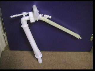
Bottom entry valve assembled
Bottom entry valve components
The ball screws onto the end of the arm, in one of two positions. Water is introduced through the inlet pipe at the top, the ball and arm rise, forcing the plunger against the black rubber diaphragm. The height of the arm can be adjusted with a screw near the plunger and the unit can be held steady by using the adjustable "leg" in the top left of the left hand photograph, to sit against the side of the cistern. These valves are also available as side entry valves.
Flushing the Loo
A very frequent question is, " My loo will not flush, the handle pulls down but nothing happens…what is wrong?"
There are only two answers…
- Your handle is not connected to the flushing mechanism in the cistern.
- The flush diaphragm is split.
A cistern allows water in through one of the above valves. When it is time to "pull the chain" the handle pulls up a plunger inside of the flush chamber. You can see the handle connection in red on the photograph below with the flush chamber to its left.
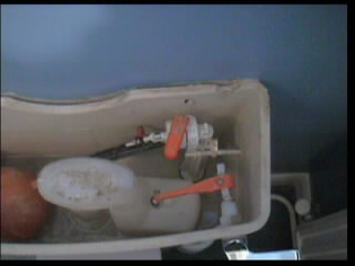
Toilet cistern internal components
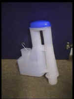
Flush chamber mechanism
As the flush chamber is full of water, this action draws up the water, retaining it in the chamber using a diaphragm. The water rises and is forced into the tube at the top of the chamber ( where the blue top is). It then falls down the other tube into the flush pipe which leads to the toilet. The action of the water falling causes a vacuum behind it, which in turn sucks up the rest of the water from the cistern. If the diaphragm (blue in the picture below) is split, which happens after continually rising and falling for a number of years, It cannot create the pressure required to force the chamber full of water up the pipe.

Blue cistern diaphragm and black mounting frame
The blue diaphragm in the picture above sits on the black frame. The water is allowed in the chamber because the diaphragm is flexible and the water can rise up through it. When the handle is pulled, the water in the chamber pushes the diaphragm onto the frame and stops any escaping as the water is drawn upward and into the outlet tubes.
A split diaphragm can be replaced by turning off the water to the cistern, flushing the toilet and soaking up any remaining water with a sponge. Once the cistern is empty, unclip the connection between the handle arm and the flush unit.
Release the back nut under the cistern and pull the flush unit clear. Unclip the bottom half of the connection clip and pull out the frame which holds the diaphragm. (There may be a spring over the central dowel, don’t forget to return this when re-assembling) Unclip and slide off the diaphragm, replace and re-assemble.
As you can tell from the above – the cold water tank and associated valves and cistern valves play an integral part in the cold water system within your home and need to be monitored and maintained to ensure correct opperation at all times.
You can also watch a video on upstairs bathroom water supply.