Main Forces
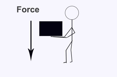
A Static Load
A good example of this is a person seen below. He is holding a stack of books in front of him but he is not moving. The force downwards is STATIC FORCE
A Static Load
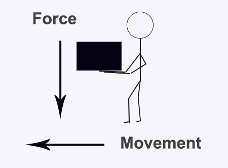
A Dynamic Load
A good example of a dynamic load is the person below. He is carrying a weight of books but walking. The force is moving or DYNAMIC FORCE.
A Dynamic Load
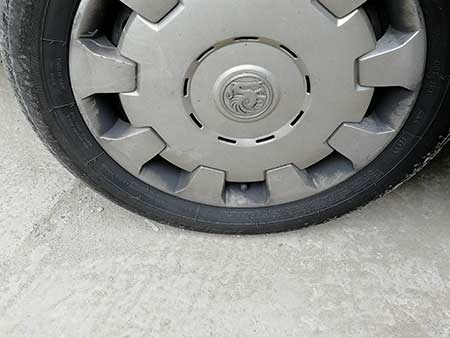
Internal Resistance
The tyre in the image below is filled with air and under great pressure. The air pressure inside it pushes back against the weight.
Internal Resistance
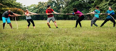
Tension
The rope is in “tension” as the people pull on it. This stretching puts the rope in tension.
Tension
Compression
The weight lifter finds that his body is compressed by the weights he is holding above his head.
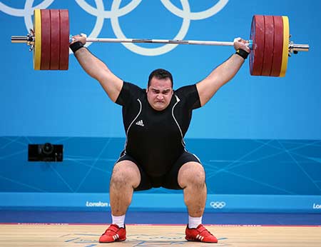
Compression
Shear Force
A good example of shear force is seen with a simple scissors. The two handles put force in different directions on the pin that holds the two parts together. The force applied to the pin is called SHEAR FORCE.
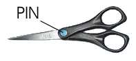
Shear Force
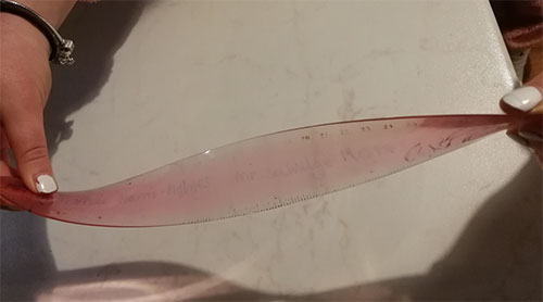
Torsion
The plastic ruler is twisted between both hands. The ruler is said to be in a state of torsion.
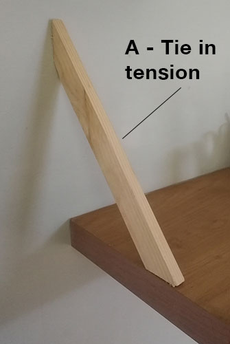
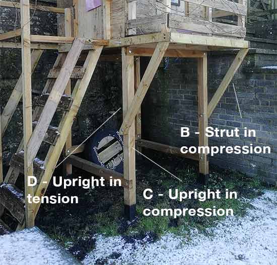
Using a kids treehouse/playhouse (when the balcony is subjected to weight) and a shelf in a kitchen we can see some different forces at work:
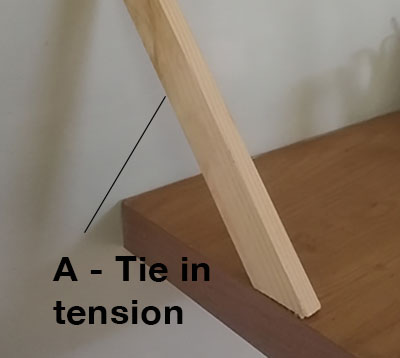
- Part A: Is in tension because the weight of the shelf and items on it is stretching it and pulling it down
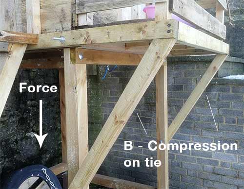
- Part B: Is under compression because the weight of the user when standing on the balcony are pushing downwards and compressing the strut
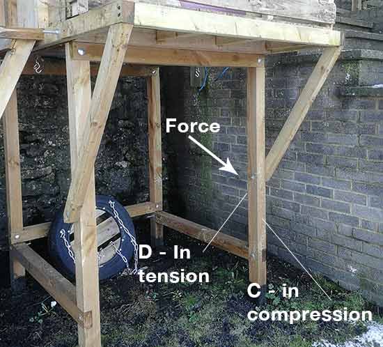
- Part C and D: These forces are applied to the same member but on the inside compression is taking place and on the outside it is being stretched (under tension)
Shelf tie with forces applied
Kids playhouse with forces applied
Forces on a Shelf With a Tie Support in Detail
When items are placed on etc shelf they weigh down on it applying stretching force to the tie support
Force on shelf tie
Weight of user on playhouse balcony compresses the support beneath.
Kids playhouse with forces applied
The vertical leg support of the playhouse bends inwards when weight is applied to the balcony area. Side “D” is stretched whilst side “C” is compressed.
Kids playhouse with forces applied
The bridge below is a common type called a Box Girder Bridge. These are usually made of steel with all the members (parts) welded, bolted or held together with rivets. Usually they are manufactured in a factory and transported to the site and dropped into position by a large crane. The triangular shapes give the bridge immense strength and for short spans this type of bridge is ideal.
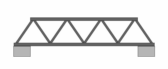
Box girder bridge
Triangulation distributes the weight of any vehicle or pedestrian crossing the bridge. The weight is distributed through all the members and so the bridge can cope with large weights. This type of bridge is favoured by the British Army. The Royal Engineers have transportable bridges like the one above that can be dismantled and transported anywhere in the world and reassembled. They are bolted together and are semi-permanent structures.
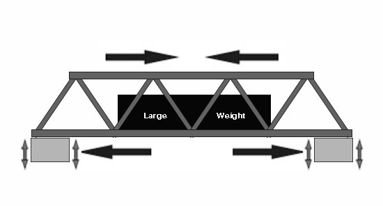
Stresses on box girder bridge
When a vehicle crosses the bridge each member experiences some type of force. The diagram shows that the member that the car rests on is under tensile force (in tension) as it stretches under the weight of the car. As the bridge bends, the top member is compress (under a compressive force).
Struts and Ties
All structures have forces acting on them. The part of the structure that has a tensile force acting on it is called a TIE and the part that has a compressive force acting on it is called a STRUT.
Wall
The beam is held in position by a steel rod. The weight of the beam is stretching the rod (tensile force).
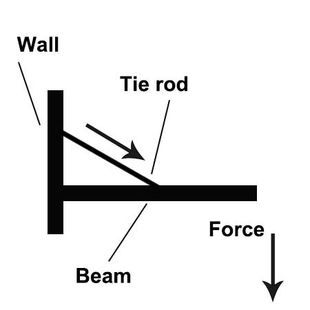
Tensile force on steel rod
Roof
The roof beams are under pressure from the weight of the tiles on the roof (compressive force). The floor beam is being stretched (tensile force).
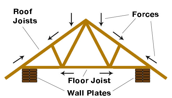
Stresses on a house roof
Flagpole
The wires on either side of the flagpole are being stretched (tensile force). Why is the pole under a compressive force ?
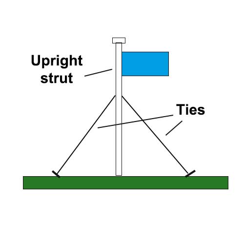
Forces on a flag pole
In the diagram below, forces act across the entire length of the beam (it bends because of the ‘ton’ weight). When a structure bends like this it is in tension as it is being stretched.
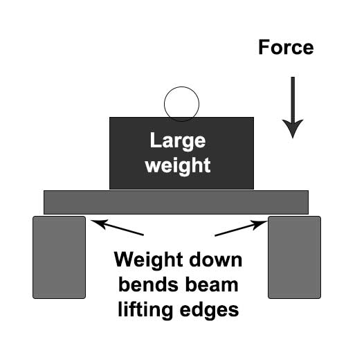
Forces act across the entire length of the beam
Levers
Levers are used to lift heavy weights with the least amount of effort. In the example below, the heavy weight on the left hand side is been lifted by the person because of the lever. The longer the ‘rod’ the easier it is to lift the weight. Under normal circumstances the person would not be able to lift the weight at all. The fulcrum is the place where the rod pivots (or rotates).
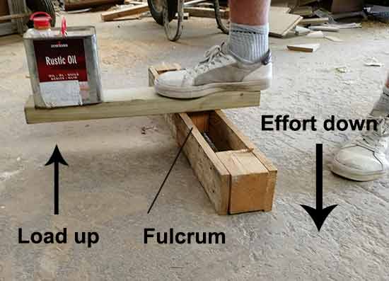
Person lifting weight using a lever system
The load is the scientific name for the weight. The effort is quite simply the amount of effort used to push down on the rod in order to move the weight.
We use levers in every day life. Bicycle brakes work due to the fact that they are based on a lever. The diagram opposite shows the fulcrum and the effort.
Another good example of a lever is a simple door handle or a wheel barrow.
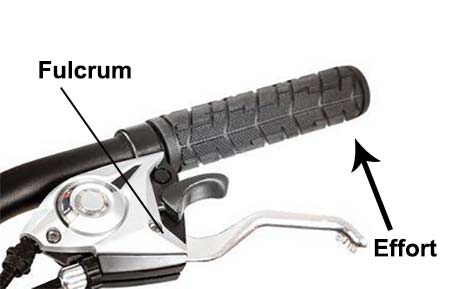
Brake lever system on a bicycle
Three Classes of Lever
There are three classes of lever and each class has fulcrum, load and effort which together can move a heavy weight.
Class 1
The workman uses a trolley to move the large packing case. The fulcrum is the wheel.
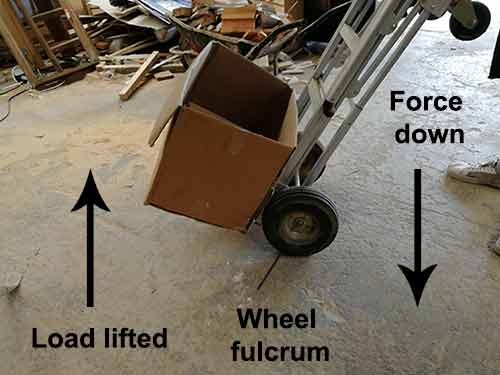
Lever system in a trolley
Class 2
The gardener uses a wheel barrow to lift tools and garden waste. The load is in the centre of the barrow.
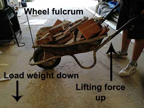
Lifting force of a wheelbarrow
Class 3
The fisherman catches the fish which becomes the load at the end of the lever.
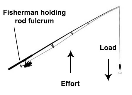
Forces involved when catching a fish