The diagram below shows a cavity in all of its glory. Not all of this goes into each cavity, but we have put everything into one to make it easier to understand.
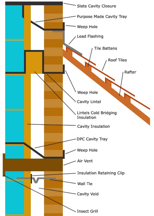
Total Cavity

Brickwork Book from Amazon
The cavity wall was introduced into buildings because it is the greatest of all damp precautions, water cannot travel across a void. Most masonry is porous to some degree, and sooner or later, especially with weak, or incorrectly constructed joints, that masonry will let in water.
Without a barrier of some kind, there is a chance that water will work its way indoors, however thick the wall. By inserting a cavity, that scenario is impossible.
or a number of reasons that we will explain below, the cavity has to be bridged. That is the two leaves, or skins, of the wall have to be connected. We will start at the bottom of the diagram and explain. At the bottom of every cavity is a foundation of some kind, this will be dealt with in another project which will include a ground floor slab construction.
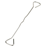
Wall Ties
The first thing we see as we go up the cavity is a wall tie, this is necessary to "tie" the two halves of the wall together and stop one moving independently of the other. An important function, but from a damp point of view, sometimes a dangerous one.
If the wall tie, which is built into the joints of the masonry, is placed so that it slopes down toward the inner skin of the building, water can run down it and soak into the inside wall.
To counteract this, firstly it is important they are installed "on the level" or even sloping toward the outside of the building. Secondly, the wall ties themselves have a kink, twist or tail, which allows water to form on this part of the tie and, given that water cannot run uphill, drip off the lowest point.
Wall tie example 1

Wall tie example 2
Wall tie example 3

Wall tie example 4
All wall ties should comply with BS. 5628 1978 the specification for metal ties for cavity walls excepting conditions where severe exposure may occur. In that case, stainless steel or non ferrous ties should be used.
Severe exposure is defined in the BS, but to be on the safe side, almost all ties these days are made from stainless steel or are galvanised. These ties should be placed at 900mm centres horizontally, and 450mm vertically.
At any openings, the ties should be placed with at least one tie, for every 300mm of height and within 225mm of the opening. This does not apply if the cavity skins are bonded together.
A cavity must be between 50mm and 75mm wide, with these figures as a minimum and maximum width.
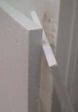
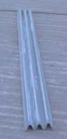
The exception to this, is when vertical twist ties (second image above) are used and spaced at 750mm horizontally. The cavity can then be enlarged to 100mm.
Both skins of the wall must be at least 90mm thick for this. A useful book covering is theBDA Guide to Successful Brickwork available on Amazon.
Cavity Insulation
Clipped onto the wall tie in the diagram, is an insulation retaining clip. Insulation can be placed in cavities in two ways. Either it can fill the cavity completely, or it can be a partial fill, as in the diagram, allowing a free air flow of 50mm for the remainder of the cavity for the reasons of moisture penetration.
The clips will stop the insulation "leaning" over and bridging the cavity. If a complete cavity fill is required, the fill must be of a composition which will totally deny the penetration of water and give it access to the inner skin.
Please check with your architect, or the building control department of your local council for the correct cavity insulation for your project. Two types are shown here, the wool, or dry and polystyrene.

Cavity Insulation
Poly Insulation
225mm Wall or Housing Tie
Wall Tie Clips
Next up the cavity is an air vent. These are found below dpc to a large degree, where a hollow floor (normally of a timber construction) needs to be ventilated. However, they are placed above damp proof courses where additional ventilation is required in a room. These bridge the cavity as a continuous duct must join the inlet and outlet of the openings. Plastic proprietary ducts can be purchased, which will, in a telescopic way, expand or retract to suit the width of the wall. The construction of this air passage can be made in individual components and some of these are shown below.
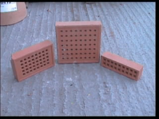
Air Bricks
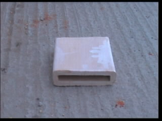
Clay Air Duct

Insect Grill
These ducts must be inserted with a fall toward the outer skin of the wall.

Brickwork 3 book available on Amazon
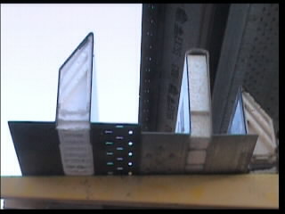
Cavity Trays
Above the air vent in the diagram, is an in situ, cavity tray damp proof course. This can be built into walls as work progresses. The object is simple, any water in the cavity will be directed, due to the slope on the dpc, to the outside wall. It will be allowed to escape via a weep hole.
This weep hole is, in its simplest form, a vertical joint (perp) void of mortar or any other jointing compound. The membrane used to form this "tray" is very often a plastic dpc, but you should check with your building inspector as to the composition of the dpc you should be using.
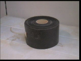
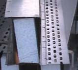
A 4 inch wide roll of plastic dpc is shown below, and these can be purchased in a number of widths to suit your project. Also shown are purpose made plastic weep vents, which are built into the void joint to allow easier passage (on a smooth surface) out of the wall.
DPC membrane
Weep Holes
An in situ cavity tray should always be inserted where it is not possible for the cavity to extend at least 150mm below the lowest level of the damp proof course. This will occur if the walls are built from a slab on or just below the surface of the ground, or, if the walls are built on a concrete ring beam supporting the property.
In all other cases the cavity must extend to a minimum of 150mm below dpc. Weep holes must be provided at regular intervals to allow any moisture collected by the cavity tray to escape. 450mm is the recommended distance between weep holes.
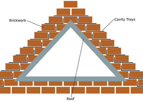
You will see a lean to roof on the diagram. When a roof abutment is added to a cavity wall (extension etc), unless the sides below the roof are open, the wall below the roof has changed from being an outside wall, to an internal one. There are very specific rules which apply to the protection of this wall from damp.
At a minimum distance of 75mm, and preferably 150mm, above the roof line of an abutting roof (flat or pitched) a cavity tray must be installed. Sometimes this is done in lead and this is acceptable, but these days, proprietary products are available which make this job so much easier.
The whole length of the abutting roof, plus at least 150mm either side must be protected from water being able to enter the cavity and run down the wall which is now within the building below it. Different types of cavity trays are available for all manner of roofs and abutments.
The diagram below shows how cavity trays must be stepped down a pitched roof. Weep holes must be provided and a lead flashing, as indicated on the first diagram, must also be provided. Once again, proprietary products cater for this, with cavity trays and flashing combined.
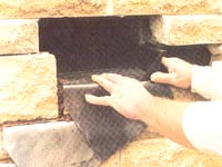
When installing cavity trays above a roof line, the bricks must of course be removed. This is done in sections with a section built up before another is exposed. The cavity trays are inserted through the hole.
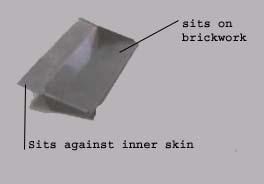
It is better if the back of the cavity tray touches the inside skin of the wall, but its not required. As long as the tray is at least 50% of the way across the cavity, it will function correctly.
Most moisture in a cavity accumulates on the inside face of the outside skin, and will run down onto the cavity tray successfully. In this position it will also catch drips from the twist in the wall ties.
Plastic Cavity Tray
Cavity Tray
Weep Holes
Roof and cavity trays

Home extensions book available on Amazon
Lintels
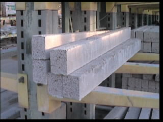
The next thing up is a lintel. Lintels need to be inserted over every opening in a wall where the wall would be weakened by that opening. The principle is that by inserting a lintel, the weight above it is transferred to either side of it. This is why a minimum of 150mm bearing must be allowed for the lintel to sit on the masonry either side of the opening.
The lintel in the picture is a cavity lintel, there are many kinds, and they are all different shapes and sizes.
To insert a lintel in a load bearing wall you are making a structural alteration and permission for this must be sought from the building control department of your local council. Yes, we know it is your house, but it needs to be safe.
If you do not get permission for structural alterations, and something goes wrong, your home insurance may not cover you and any future buyer may reject the property on a surveyors advice.
Insulation is provided within a cavity lintel to stop what is called "cold bridging". This is the transference of outside temperatures to inside walls leading to cold spots and subsequently increased condensation on those spots (See our condensation project for further information).
Cavity lintels, for the most part, are designed to carry any water in the cavity to the outside skin, again through weep holes, but where a cavity tray dpc is used in conjunction with lintels, as must be the case with reinforced concrete, or box lintels, the dpc must extend 150mm either side of the end of the lintel.
Cavity Lintels
Reinforced Concrete Lintels
Box Cavity Lintels
Lintels can be bought to suit all standard size openings, they can be made to suit non-standard openings or larger ones can be cut down.
Double Skin 9" Lintel
Internal 4inch wall lintel
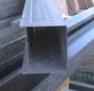
Box lintel
Closing Cavities
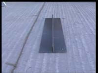
Above the purpose made cavity tray, you will see a piece of slate that closes the cavity. Cavities must be closed at all points where there is a risk of fire spreading to another part of the building.
In the most part, this must be done with a non combustible material or at least one (where specified by an architect) that has a 30 minute fire protection rating.
Cavities are closed at the termination of the wall at roof height, at the sides and head of any opening, doors, windows, meter boxes, (the head is generally protected by the lintel, but where two concrete lintels are used, the gap between them must contain a fire barrier). Purpose made cavity barriers are available for this work.
Where a cavity is closed vertically, it is most often done by using the bricks or blocks that the wall is built from. This would of course bridge the cavity and a vertical damp proof coarse must be installed. Diagram drawn from above.
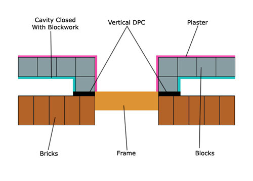
Closing Vertical DPC