Correctly installed, an exterior socket is a very useful facility to have. It means you no longer have to run extension leads from inside the house, with the potential for tripping over them!
It enables you to run electric garden equipment such as a lawn mower, hedge trimmer and various other items including power tools, in a far safer way. In fact it is wise to have one at the back and one at the front of the property, which can be used for car washing equipment, power washers and other items such as vacuum cleaners.
In this DIY guide we go through the steps involved in how an outdoor socket is installed.
Regulations on Installing Outdoor Sockets
As we are dealing with electricity outdoors there is always the potential for it to come into contact with the elements, namely water and moisture. Due to this, an outdoor socket should be at minimum IP66 rated, making it water and dust resistant.
Additionally, any outdoor socket MUST be protected by a 30mA RCD e.g. it must be wired off of a 30mA circuit with an RCD in your consumer unit. However if this isn’t the case then the socket itself must have its own RCD built into it.
Despite the above, although it’s possible to spur off of an existing 30mA circuit, generally the belt and braces approach is to install a separate RCD/fuse that supplies only your new outdoor socket.
Also, although if protected by a 30mA RCD you don’t need the socket itself to have its own RCD, again belt and braces is to ensure it does. This way, you’re doubly protected in the event of any issues.
When it comes to RCD’s, it will very much depend on the type of consumer unit or fuse board you have as to whether it has 1 RCD protecting the whole board, 2 RCD’s to create what’s known as a zoned board or no RCD’s at all, but your electrician will know this and install the circuit accordingly, even if that means having to install an RCD also.
One final point to make is that if you need to run any cable externally to an outdoor socket, it again MUST be protected, meaning you should only use SWA cable.
With this in mind, the installation of an outdoor socket should only be carried out by an experienced and qualified Part P registered electrician that has the skill and knowledge to do it correctly, test it and then sign it off with a minor works certificate when complete.
Failure to comply with these rules can invalidate your home insurance and also make it tricky to sell your home.
As we all know, working around electrics is very dangerous so to find out how the pros do this safely, check out our electrical safety project here.
Where Should you put an Outdoor Socket?
Where you sight your exterior socket is extremely important. You want to ensure it is in a place where it is easily accessible when needed, fixed to a solid, stable surface and also on the right side of the house.
By this we mean, if you have both a front and back garden then you’ll need to decide where it will be most useful, unless you want to get one installed in both areas.
Another factor is how far away from your consumer unit the plug will be. As an outdoor socket will need to be supplied by a 30mA RCD protected circuit, you will need to run your supply cable from the supply (normally the consumer unit) to the install location.
If your consumer unit is quite far inside your home then you may need to start drilling holes through walls or running cables up through floors, which can get expensive and involve a lot of hassle.
So, generally the closer you can install your socket to its power supply the easier the installation will be.
Do Outdoor Sockets Need to be Waterproof?
As an outdoor socket will be exposed to the elements e.g. water and moisture, to prevent it shorting out and causing untold issues with your home electrics it needs to be sealed and protected. To these ends, it should be at minimum IP66 rated meaning that it is waterproof and resistant to any dust ingress.
In the event of any issues, the fact that the circuit is protected by an RCD on the circuit it’s fed from and also hopefully by the fact the socket has its own in-built RCD, it should trip and prevent any issues or injuries.
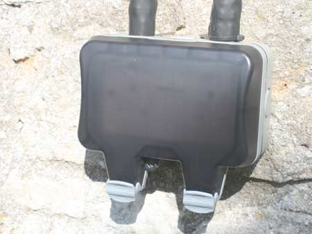
Closed and sealed outdoor double socket
Types of Exterior Socket
There are many different types of exterior socket available on the market today, some cheap, some rather more expensive. Generally as with most things, you get what you pay for.
When it comes to an outdoor socket, due to the potential levels of danger you should always opt for the more expensive and fully featured sockets, or the best you can go for, for the budget you have.
As stated above, if it you don’t need it as the circuit feeding the socket is up to the required specs, you should always go for one with its own in-built RCD.
The more expensive options, as well as incorporating an RCD, will also feature a front cover which will encapsulate the 13 amp plug and start of the cable, when the cover is clicked shut. This both fully protects it from any water or moisture and prevents the plug being accidentally pulled out.
Finally a socket of this calibre will also ensure an IP rating of 66, which really is the very minimum you should be going for. More information on IP ratings can be found in our bathroom lighting project here.
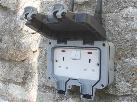
IP66 rated outdoor socket with fully sealed opening cover
Tools and Materials Needed for an Outdoor Socket?
In terms of what products and materials should be used to wire up and outdoor socket, these are as follows:
- Minimum IP66 rated outdoor socket with in-built RCD
- Consumer unit RCD – to add to consumer unit, if not spurring from existing 30mA circuit
- 30mA junction box – If creating spur
- FCU (fused connection unit) – if taking a spur
- Suitable length of 3-core SWA cable plus clips – if running externally to socket
- Glands for SWA cable connection
- Electrical side cutters
- Wire strippers
- Flat head screwdriver
- Philips screwdriver
- Drill/driver
- Suitable screws
- Wall plugs
- Masonry drill bits
- Large masonry drill bit – if drilling thorugh external walls
- External silicone sealant and sealant gun
- SDS power drill
- Pen/pencil for marking holes
- Flat drill bits – for drilling out socket blank plug if needed
- Spirit level
- Adaptor box
- Earth tape/sheath
- 32 Amp MCB
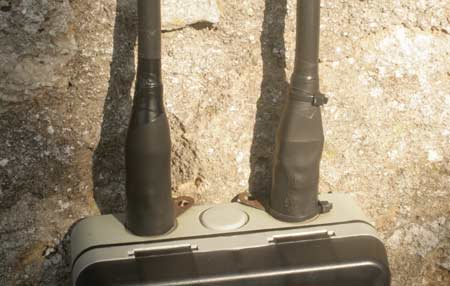
Supply wiring for outdoor socket
Installing an Outdoor Socket
For the purposes of this example, our electrician will be wiring up an outdoor socket in a rear garden, some way from the property so will be running SWA cable to the location.
As there isn’t an available 30mA circuit, he will also be installing a new MCB in the consumer unit that itself will be protected by the required RCD as it was a zoned board and has 2 RCD’s built in.
In this case the consumer unit it located in the kitchen on an outside wall so he can simply drill through the wall to run the supply cable.
Step 1 – Drill SWA Cable Hole
The first job is to drill a suitable sized hole through the external wall near to the consumer unit. The drilling position was first marked on the wall and then an SDS power drill and suitable sized drill bit, large enough for the SWA cable to comfortably fit through were used to drill carefully through the wall.
Once the hole was formed it was then cleaned of any sharp/rough edges as not to snag the cable.
Step 2 – Run SWA Cable From Consumer Unit
When running SWA cable, as commented, you should make the run as short as possible and try to avoid making any very sharp turns.
A it’s not easy to fix SWA cable directly into a consumer unit, it is good practice to first run to an adaptable box usually sighted next to the consumer unit, where a glad can easily be fixed in place and then from there a suitable piece of 2.5mm twin and earth is run to the consumer unit.
First, the adaptor box is fixed to the wall, a gland is fixed in place and then SWA cable run in, secured and stripped in preparation for connecting to 2.5mm twin and earth.
The SWA cable is then slotted through the drilled hole and carefully pulled down to the install location.
Step 3 – Fix SWA Cable to Wall
Next, a direct route to the outdoor socket is planned and cable clips fixed to the wall or surface the cable is being run along.
All cable clips are fixed horizontally level to create a nice visual finish and the cable is then fixed into each clip.
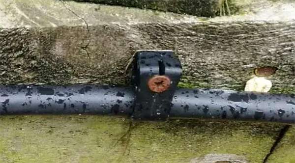
SWA cable installed into cable clips
Step 4 – Strip SWA Cable
The next step is to strip the end of the cable and then connect it up to the socket.
The first job is to calculate the length of the inner insulated wires which will fit through the cable gland, into the socket box and then to the terminals within the socket. Generally, a minimum of 250mm (10 inches) is required.
Cut an appropriate amount of the outer covering of the cable using a trimming knife. Peel away the outer covering which will expose the many strands of steel wires.
Beneath these steel wires is the inner core cable, which has a similar protective covering. Using a pair of good quality side cutter pliers, or nippers as they are sometimes called, from the point where the outer covering has been cut, judge 20mm (3/4 inch) and cut each strand of the outer steel wires. The inner exposed wire will be around 250mm long at this stage.
From the point where the cut steel wires are, measure a point 50mm along the inner wires which have the protective covering.
With great care, so as not to cut into the insulated current carrying core wires within, remove the outer covering to expose the insulated core wires.
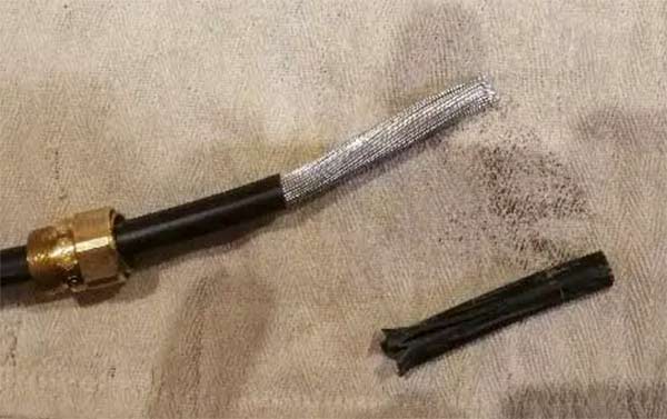
Outer SWA cable stripped back
Step 5 – Add Cable Glands
As we have stated, to ensure everything is completely sealed, SWA cable is connected and secured to the exterior socket box by glands. The glands are commonly brass, with a retaining washer and a securing nut. The gland is tapered to allow for the steel wires of the cable to be secured to the it via a brass nut.
A 3 core SWA cable of the 2.5mm2 sort would be 18mm outside diameter (O/D), so you would then need to use 20mm connecting glands. The exterior socket boxes usually have round knock out openings.
Having chosen where the connection will go to, this is determined by where you will run your cable in, either side, top or bottom, the desired blanking plug is then pushed or in some cased drilled out.
Glands from electrical suppliers are usually sold in pairs, one for each end of the cable and also come with a weather-proof sheath, a tapering conical item that is cut to suit the cable size and then the wire fed through this hole.
Next, slide on the external nut which will secure the cable to the gland.
Connect the male threaded part of the gland into the knocked/drilled out hole in the exterior box. Fit the retaining washer, from the inside and secure the gland to the box with the brass securing nut. Tighten to secure without over stressing the connection.
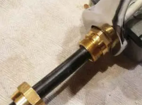
Cable gland fixed to adaptor box
Step 6 – Insert Cable into Glands and Connect Socket
Next, feed the insulated wires and the SWA through the gland into the box.
The conical end of the gland should now meet with the steel wires which are approx 20mm long. Hold the wires with one hand from inside the box, slide along the brass exterior retaining nut to fit over the steel wires, to the treaded part of the gland exposed and tighten up, hand tight at this stage.
Next, 10mm or so is stripped form the end of each core wire and they’re then connected into their respective live, neutral and earth terminals in the socket itself. Earth sheath was also slipped over the earth wire as required.
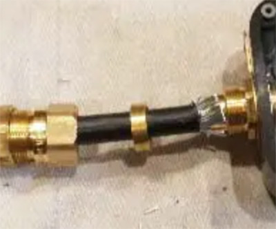
SWA cable inserted into glad and pushed up
Step 7 – Fix Socket and Box to Wall
Ensuring the inner wires are not kinked, position the socket box and housing up to the surface it’s going to be fixed to, level it up using a spirit level and then mark the fixing holes.
Using a suitable sized drill bit and a drill, drill out the holes, insert wall plugs and then screw the unit to the wall using suitable sized screws.
Next, pop the socket faceplate in place on to the socket, insert the fixing screws and screw them up nice and tight, but not too tight.
Using a spanner or crescent wrench of the appropriate size, tighten the exterior gland nut and then slide the protective sheath over the base of the gland to provide a good seal against the elements.
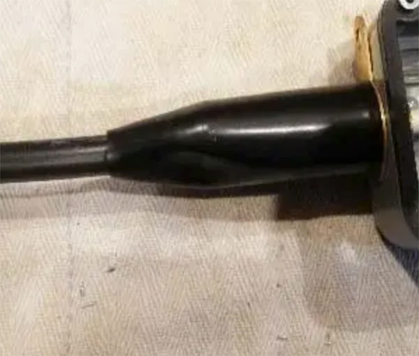
Slide sheath up over gland on base of adaptor box
Step 8 – Connect Adaptor Box to Consumer Unit
Once the socket is fixed in place, the final job is then for the electrician to make the final connection between the adaptor box and the consumer unit.
As stated, there was no available 30mA circuit to connect to so it was necessary to install a new one so that the socket would have it’s own to run off of.
Before any installation took place, the entire consumer unit was switched off to isolate everything and prevent any injuries. As larger MCB’s should be placed as close to the RCD/main switch as possible, it was necessary to move the other MCB’s down slightly to fit the new one in.
To confirm, the wiring is connected to a 32 amp MCB which itself is installed under an RCD that fully protects it, giving us the required protected 30mA circuit.
Each one was loosened and then slid down the din bar. The new MCB was then put in place and the others were then secured.
A suitable length of 2.5 twin and earth was then cut to length to run from the MCB to the adaptor box. It was then stripped off at both ends. One end was then connected into it’s new MCB and the other was then joined up to the incoming SWA cable in the adaptor box correctly.
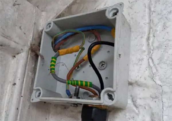
SWA cable connected to cable running to consumer unit
Step 9 – Test Circuit
Once all connected up the final job was then to turn the power back on and test the circuit fully to ensure all was correct.
Once the electrician had performed the necessary tests, he then signed the work off and issued a minor works certificate to confirm everything was done to the required regulations.
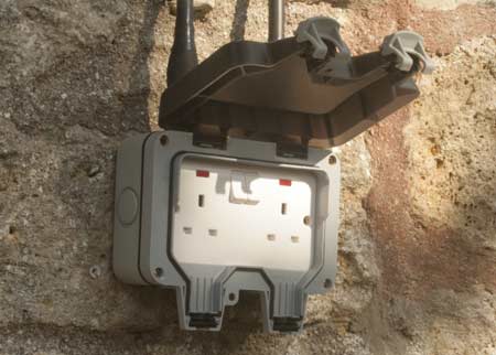
Securely fixed and finished outdoor socket

