The basis of Approved Document J is to provide help and guidelines on all things to do with combustion appliances and fuel storage systems and to ensure that any appliance that involves combustion is installed and run in a safe manner and any fuel that is either used to power such appliances or is stored is done so in a safe way.
Approved Document J of the Building Regulations – Download it here
As there are quite a few items covered within this document it is broken down into the following seven categories:
- J1 – Supply of air
- J2 – Discharge of combustion waste and by-products
- J3 – Carbon monoxide warnings
- J4 – Building protection
- J5 – Providing information
- J6 – Liquid fuel storage safety
- J7 – Pollution protection
J1 – Supply of Air
The process of combustion needs oxygen in order to take place and due to this any appliances that burn a fuel need a good, constant supply of air so that whatever they are burning (gas, fossil fuel etc….) burns in the correct way.
Where an appliance does not feature a flue, such as a portable gas fire, then this will also need a good supply of constant moving air so that any combustion by-products are removed from the air within the room and vented outside of a building. This will prevent a build-up of dangerous gasses such as carbon monoxide.
Additionally, most flues also require a decent air supply to work effectively as their ability to suck combustion waste up and out of a building relies heavily on the "draw" of air from an outside source.
Due to the above, in most cases combustion appliances will require an air vent to be fitted somewhere within the room. The size of a required vent will very much depend on what fuel type is being burned (normally judged on the fuel that gives the highest heat output) and the number of combustible appliances in the room (one vent or set of vents per appliance – needs to be increased on the addition of more appliances).
Where an open-flued appliance is present it may require constant air flow meaning that any ventilation will need to be permanently open (this will depend very much on the type of appliance, the type of fuel, the manufacturers recommendations and the rules stated by any relevant approved document).
When an open-flued appliance is enclosed then in most cases the enclosure itself will also need to be ventilated so that air flow from within the room space outside can also pass into the boxed in area. Any points of ventilation will need to be of the correct size to provide enough combustion air and also air for flue operation.
Like-wise, where certain appliances are room-sealed and it’s combustion air comes from another area of the building or the flue itself opens into another space, that space should also be ventilated permanently to the outside but when a flueless appliance is involved, any vents for this should go directly to the outside air.
J2 – Discharge of Combustion Waste and By-Products
As we mentioned, some appliances do not feature flues and will emit any by-products of the combustion process into the surrounding air of the room it is in, such as a portable gas fire. These appliances require a suitable amount of circulating fresh air to get rid of any fumes and prevent the build-up of dangerous gasses.
Where an appliance does have a flue there are certain rules stated that the flue must comply with:
- Flue Size: The size of the flue pipe that fixes to an appliance should be the same diameter as the flue pipe outlet that is present on the top of the appliance itself or the correct size stated by the manufacturer
- Flue Height: This refers to the total length of the flue (from where it is attached to the appliance to where exits the building). In general, the flue needs to be long enough to ensure that a sufficient enough draught is created to clear any by-products. This will very much depend on the appliance type, the flue type and number of bends it has, how high the building is and surrounding wind patterns
- Flue Exit: It must be ensured that the flue itself exits the building in such a way that it is above the roof and makes sure that any vented by-products can be dispersed freely into the air. Its position and height may need to be adjusted slightly where taller surrounding buildings, trees, higher ground or strong winds are present
- Thatched Coverings: Due to the flammable nature of a thatched roof, any flues exiting onto a thatched roof should have their clearance increased. Heat transfer from the flue/chimney onto the thatch itself also needs to be taken into consideration and special measures will need to be put in place if there is risk of spontaneous combustion
Additionally, it is also stated that the fluepipe itself can only be used to physically connect an appliance to its own specific chimney. They are not allowed to run through any internal wall, separating partition, roof void etc…. unless they are going to pass straight into a chimney.
Flues can also get rather hot and due to this the rules also state that if a given flue is exposed and poses a risk of burning then it should be surrounded with a guard.
As chimneys and flues are exposed to the outside then there is a potential risk for items to find their way into the flue or chimney space and fall down. Due to this it is also stated that accessible cleaning points need to be provided in appropriate locations if cleaning cannot take place through the appliance itself.
J3 – Carbon Monoxide Warnings
As we have already discussed, the ignition and burning process needs the correct amount of oxygen for the situation required and also in most cases some continuous air movement. If a given appliance does not receive the manufacturers/building regulations stated required amounts then it may not burn its fuel source cleanly and will produce harmful fumes and gas, in most cases, carbon monoxide.
In light of this, Approved Document J states that when a solid fuel buring fixed appliance is either installed in a building as a brand new installation or installed as a replacement for an old appliance, a new carbon monoxide alarm should also be fitted within the same room.
When it comes to carbon monoxide detectors themselves, the following rules apply:
- Need to comply with BS EN 50291:2001
- Where powered by battery, the battery should be designed to last the entire life of the alarm itself
- Should also incorporate an alarm to warn when the life of the battery is coming to an end
- When powered by mains, the alarm should also comply with BS EN 50291:2001 and also be fixed wired without a plug. This type of alarm should also feature a warning device for sensor failure
- Has to be situated in the same room as the appliance
- Fixed to the ceiling with a minimum of 300mm from any surrounding walls
- If wall fixing is the only option, should be fixed up as high as possible but should be outside of 150mm from the ceiling
- Should be fixed between a distance of 1 and 3m from the given appliance in a horizontal direction
J4 – Building Protection
This section of the document shares a few similarities with section J2 as this is to do with the protection of the building and it users from any and all appliances, flues and chimneys.
It is essentially in place to make sure that no users within the building are harmed and the building itself is not at any risk of catching fire due any featured appliances, their venting mechanisms, fuel storage requirements or the way in which they have been installed.
This particular section covers both appliances that attach to a flue (e.g. a central heating boiler) and also a fireplace and its associated chimney (e.g. open fire).
J5 – Providing Information
This section of the document is concerned with notifying any relevant persons about the way in which flues, chimneys and hearths have been installed within a property and to what extent they can be used. If any of these items have been altered as part renovation or home improvement work then this information must also be stated.
In terms of stating this information the rules state that it must be displayed in an obvious position such as next to near a chimney or flue or somewhere such as next to an electricity meter or consumer unit.
The document also states that any notification should be hardwearing (to avoid damage or confusion), should be marked in permanent ink and it should also be securely fixed in its location.
The notice itself should state the following items:
- Where the fireplace is located and also the hearth or where any flues start
- The date when installation took place
- What category any flue falls under and what types of appliances can be used with it
- What type of flue is installed, its dimensions and who manufactured it. If it has been relined at any point then the previous information must be stated for this also
In some situations certain chimney items will have been assessed against European Standards and will be marked accordingly. If this is the case then this information can also be stated on the notice
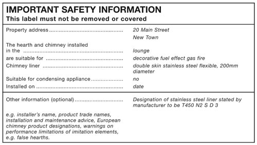
An example notice stating safety information for flues and hearths – Image courtesy of Approved Document J of the Building Regulations
J6 – Liquid Fuel Storage Safety
This area of the document is mainly concerned with the storage of liquid fuel types and how it is then transported from its storage location to the appliance needing it in the safest way possible. There are also elements of section J7 covered here but these will be covered in more detail in the next section.
The first item dealt with in this section is the use and storage of heating oil. In respect to this, heating oil is defined under section 5.2 as one of the following:
- Class C2 oil or Kerosene
- Class D oil or Gas Oil (specified in BS 2869:1998)
- Liquid biofuels (those that conform to EN 14213:2003)
- Liquid biofuel and mineral oil blends
This requirement (J6) is concerned with all storage systems no matter what size they are (over 90 litres storage capacity) and regardless of the type of building they are serving. There is no stated maximum size of tank where this requirement does not apply and it also applies to both above ground tanks and buried tanks.
One of the main points of J6 is to protect a building from the potential fire risk that a tank of liquid fuel poses and to also ensure the tank itself is accessible and maintained. To these ends the following is stated:
- An above ground tank should sit on a hard surface such as a concrete base of paved surface and should be a minimum of 42mm thick. The base should also extend a minimum of 300mm beyond the edges of the tank
- When sited within a building a tank be situated in a part of the property that is designated as a place of special fire hazard. It should also be ventilated directly to the external of the building from within that space
- When sited less than 1800mmm from any part of the building all surrounding walls should be imperforate with a minimum of 30 minutes fire resistance
- When sited less than 1800mmm from any part of the building a fire wall can be built to shield the building from the tank. The wall itself should extend at minimum of 300mm beyond the dimensions of the tank including its height
- When a tank is situated less than 760mm from a boundary a fire wall should be constructed that has a minimum of 30 minutes fire resistance and is at least 300mm wider and higher than the tank
When it comes to the supply pipework for an oil heating system, all pipework should be fire resistant and a fire valve should also be fitted as part of the system (as recommended in BS 5410-1:1997)
Also covered under this section is the storage of LPG. The legislation that covers this type of tank is stated by the HSE. Due to the nature of this type of fuel there can be other numerous factors that affect what safety measures need to be put into place but in general if the guidelines stated in Approved Document J are followed (and those relevant sections of Approved Document B) and the tank is above ground and does not exceed 1.1 tonnes in its capacity then it should be fine.
To summarise, the following points need to be met:
- Tanks need to be installed outdoors
- Should be sited in a location that is separate from any surrounding buildings and their boundaries or anything that is likely to pose an ignition risk (in the event of a leak this will allow gas to safely escape into the air)
- If a fire is caused then separation from any properties etc…. should ensure that it does not spread
- Any potential entrances into a building that fall between the tank and the building such as drains, basement hatches etc…. should be sealed in such a way that gas cannot enter
- Any fire wall should be constructed from concrete or solid masonry and should be fire resistant form a minimum of 30 minutes. If the fire wall forms part of the property then it should give at least 60 minutes fire resistance
In some situation, LPG can be stored in cylinders. if this is the case then you will need to meet the following guidelines:
- All cylinder should be stored in the upright position
- Should be chained or strapped to an external wall of the property
- Should be sited outside
- Should be stored at ground level
- Should be protected from any potential physical damage
- Should not obstruct any exits from the property
- Should be stored on a solid base of concrete or paving slabs at least 50mm thick
- On a horizontal line, they should be a minimum of 1m from any openings or sources of heat and 2m from any drains and vertically they should be at least 300mm from any openings or sources of heat (e.g. flues or chimneys)
When it comes to the supply pipework for any LPG system the following guidelines need to be adhered to:
- Any pipework running underground should be corrosion resistant
- Any pipework that enters a property or building should be made from metal
- Where a plastic (or other material pipe) joins with a metal pipe to run into a property, the join should be on the outside of the property
- Pipes entering a property should always enter above ground and in a sleeve
- Any sleeving should be one piece and travel the entire length of the distance through the wall and also should be sealed on the inside to prevent any gas leakage from entering the property
- When pipework runs should any form of shaft or void, the shaft or void itself has to have suitable ventilation to allow any leakage to vent safely and externally
J7 – Pollution Protection
The basis of this section of the document is concerned with the potential pollution risks that storing fuels can have and it is mainly focused on and around the storage of fuel oil.
In essence, the guidelines state that:
- Any items included in the system (storage tanks, pipework etc….) should be constructed from fire resisting materials and should also be sited so that they are not exposed to any potential fire risks
- Storage tanks and pipework etc…. should be as damage resistant as possible and any leakage during filling or maintenance of the tank should be as reduced as possible
- Feature a secondary containment system
- Should feature information on what to do in the event of a leak
When dealing with the installation location of a tank e.g. above ground or below, it is recommended that a tank should not be installed below ground as they become very difficult to maintain and if they start to leak it may be some time before this is noticed.
As you can imagine there are quite a few factors that can determine how risky a certain installation is. In respect to this the following are considered to be of a higher risk factor:
- The total capacity of a given tank is over 2500 litres
- Tanks that are located within a 10 metre area of freshwater or costal water sources or within 50 metres of a water sources such as wells or springs or areas where any leakage can reach any affore mentioned water source by travelling over hard ground
- If any leakage can potentially run into the drainage system through unsecured or loose manhole covers or open drains
- Where any vent pipes for the tank cannot be seen from the filling point
- Is situated within an area identified as Zone 1 of an SPZ (Environment Agency Groundwater Source Protection Zone)
Bunding is also a very important factor when dealing with above ground tanks. A bund is a kind of tank that surrounds the actual tank inside it. It is designed to catch any spillage (if using a single skinned tank and the tank sits within the bund itself) or if the bund is integrated into the tank, this is kind of tank that surrounds the actual tank e.g. a second skin. Again, if the main tank develops a leak the surrounding tank or bund will contain any leakage.
In either case the bund itself should be designed and constructed to hold at least 110% of the volume that the actual tank holds, ensuring that in the case of a major leak all the contents can be contained.
As stated above, any oil storage facilities should feature detailed information covering exactly what to do in the event of a leak.
As stated in previous project pages covering Approved Documents, the above information is meant as a guide only so if you need to reference Approved Document J for any building or home improvement works please ensure that you download the most up-to-date document from the Planning Portal website on the link above.