Since its introduction, the consumer unit has now become the product of choice for distributing electricity around your home due to it’s simple layout and relatively straight forward setup (if you’re an electrician and know what you’re doing obviously).
In this guide we take a look at the consumer unit and how it works, read on to find out more.
Rules and Regulations for Electricity in Your Home
As we are all taught from a very young age, electricity is extremely dangerous and if you don’t know what you’re doing with it, working on or around it should be left to the professionals! This is certainly no different when it comes to consumer units.
To allow you to do any electrical work in your home, other than changing existing switch and socket face plates, you need to be what’s known as a “competent person”. What this means is that you have the necessary knowledge and skills to install, fully test and then issue a works certificate for any electrical work carried out in the home.
When it comes down to it, the only person(s) able to do this are those that are Part P registered. If however you ignore this and do carry out electrical work that you’re not allowed to, this is illegal and also can invalidate your home insurance and cause potential issues when trying to sell your home.
Additionally, it’s also worthy to note that there are regulations as to where sockets and switches can be placed, see our socket height project here for more help.
Also you should be aware that some years ago, the standard wire colours used in the UK were changed so that they harmonised with those used in Europe so you may have several different colours of wire in your home. See our wire colours project here for more information.
For further information on staying safe when working around electricity, see our electrical safety project here.
One final point – If you still have an old style fuse box as opposed to a consumer unit, then this almost certainly won’t be compliant with the latest wiring and electrical regulations so you should think about getting it changed for a much safer modern consumer unit as soon as you can.
The Consumer Unit – What is it?
The modern consumer unit is the centre, or heart, of the wiring system in the home. The unit distributes the electricity, via newer RCD’s and MCB’s that replace the older fuses, to all of the different circuits used in your home such as the sockets, lights, cooker and any others.
Traditionally, electricity was distributed around a property by using a fuse board. This is similar in principle to a consumer unit but as opposed to using RCD’s and MCB’s, each circuit is protected using a fuse (similar in principle to a standard cartridge fuse found in a plug).
When a fuse gets overloaded and blows the piece of wire running between the 2 poles burns out to cut the power. Once the issue causing the overload has been resolved, the piece of fuse wire is simply replaced and the fuse popped back into the board.
Although this system is fairly straight forward, it does rely on the correct size fuse wire being put back in as if it isn’t then this could be highly dangerous as it may not burn out and cut the power correctly!
To do away with any potential issues such as these, the older fuse wires have been replaced by their modern equivalent, the MCB or miniature circuit breaker.
This handy object takes the place of the traditional fuse and when it senses overload it simply flicks the switch off, cutting the power. Once the cause of the trip has been resolved, the MCB will then allow you to turn the power back on again.
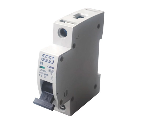
Modern MCB used in place of a traditional fuse
The modern consumer unit also has a range of other safety features including a main switch that controls the power to the entire unit, that, once switched off, will turn the power off to the entire house.
They can also feature 1 or even 2 RCD’s. The RCD, or residual current device is similar to an MCB in that if it senses an issue it will trip and isolate all the of the MCB’s/fuses below it. More on these below.
More recently RCBO’s have since come onto the scene. These are essentially a combination of an MCB and RCD so provide additional safety levels. Also they resolve the nuisance tripping issue highlighted in subsequent versions of the Wiring Regulations.
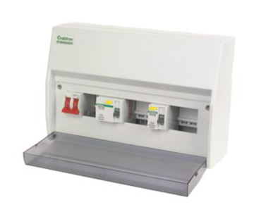
Consumer unit with 2 built in RCD’s
The Anatomy of a Consumer Unit
Now that you know exactly what a consumer unit is and what role it plays in terms of the electrics in your home, it’s time to look at it in a little more detail so that you know the role of each component inside.
The image below is of what’s known as a split load board. This is where it features a main switch for the entire board plus at least 1 RCD labeled as “E”.
According to the BS7671 Wiring Regulations, currently 18th edition, it states that a 30mA RCD may feature in a consumer unit to provide additional protection for the circuits running off of it, but it must not be the main means of protection. Each individual circuit (e.g. lights, sockets etc.) must in turn be protected by it’s own MCB or RCBO.
Today, many consumer units that are installed will feature at least 1 RCD, sometimes 2 as this is really considered to be the “belt and braces” approach. If not, then most likely today, each circuit will use an RCBO.
As there are so many homes that feature at least 1 outdoor light or power socket, lighting in or around the shower or featuring circuits that need additional protection, single load boards are rarely used, opting mostly for the more secure split load board or RCBO, more on all of this below.
Getting back to our more in depth look at the internals of a consumer unit, for this example we have used a basic split load board (as seen in the image below):
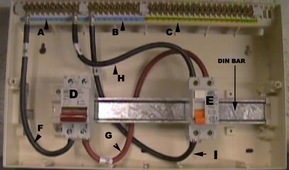
The basic components of a consumer unit
The key to the above image is as follows:
- A: Neutral terminal block for the main isolating switch side of the unit
- B: Neutral terminal block for RCD side of the unit
- C: Earth terminal block (takes both sides of unit)
- D: Main double pole isolating switch
- E: Generally 80 – 100 Amp RCD with 30mA (milliamp) sensitivity
- F: Neutral link cable from Main switch to terminal block
- G: Live feed from main switch to RCD
- H: Neutral link cable from main terminal block to RCD
- I: Neutral link cable from RCD to RCD neutral terminal block
- DIN Bar: the bar that holds each RCD and MCB in place
Along with an MCB for each circuit and the wiring required to wire up each MCB (more on this below), that’s pretty much it in terms of what you’ll find in a consumer unit, however there are some exceptions depending on what it’s serving, whether it’s domestic or industrial etc.
Just as a matter of interest, DIN stands for Deutsche Industrie Norm and, originating in Germany, is any of a series of technical standards, used internationally, to designate electrical connections, film speeds and paper sizes.
What are the Different Types of Consumer Unit?
There are 4 main types of consumer unit setup found in UK homes today; The single load consumer unit, the split load consumer unit, the consumer unit with RCBO’s and the High Integrity Consumer Unit:
Single Load Board
The first type is the single load consumer unit. This is where the incoming mains power is first taken through a double pole isolation switch, which then in turn feeds a live bus bar that supplies each MCB on the board.
Each MCB is installed by clipping it onto a DIN bar and the "teeth" of the bus bar are inserted into the base of each MCB. This carries the live current into the MCB and the cable that supplies the given circuit are connected to the top section.
The major difference between this type of consumer unit and the below type is that this one does not feature an RCD’s so in terms of it’s relevance today, is now considered a little old-hat!
Despite this there remains many still in use in many homes across the UK today, however whether they are still legal very much depends.
Essentially, if an EICR (Electrical Installation Condition Report) is carried out on such a setup and it is found that everything is working as it should be then all should be well, as long as there are no outside or zoned circuits that require an RCD.
In terms of the law, RCD’s are only required to be installed in a new build, where additions or major alterations are done to an existing property or when a rewire is carried out.
In most cases, to add an RCD to an existing consumer unit, it’s much easier to simply replace the entire consumer unit, as space is often an issue. This is obviously a costly job and if it’s not necessary then it’s a cost that can be avoided. However, due to the added protection that they give, it’s a great idea to do it as and when you can.
Split Load Board
When the 17th Edition Wiring Regulations were introduced in 2008, it stated that all circuits should be protected against earth leakage and to ensure this is the case, the split load consumer unit was introduced.
A split load board is designed for total safety and incorporates an RCD (Residual Current Device, shown as E in the picture above) as well as the double pole switch (D).
The split board shown here has one RCD and is a simple version to show the user how the board works, however most modern split load boards feature 2 RCD’s.
An RCD is a manually operated isolator switch, but it is also an automatic safety device that will trip and cut off as soon as it senses an earth fault, or indeed earth leakage.
RCD’s also work by detecting an imbalance between the Live and the Neutral conductors and this feature is a requirement for all Class 2 double insulated equipment.
As they are very sensitive to the slightest bit of earth leakage, it is not practical to fit one RCD to protect the whole house, hence the reason they are split over 2 circuits, normally one upstairs and one for downstairs.
This layout ensures that all areas are fully protected, including showers and cookers, but if one trips the second circuit should still be operational so you still have lights and power if needed.
One very interesting point to note is that as of the issuing of the second edition of the BS7671 18th Edition Wiring Regulations, it introduces section 531.3.2 concerning unwanted tripping and how to minimise nuisance tripping in the home.
This seems to suggest that moving forward, RCBO’s should be used for individual final circuits as opposed to RCD’s as the earth leakage across several appliances on the same RCD could be enough to tip the balance and cause nuisance tripping, especially where washing machines, dishwashers and the similar that can earth leak quite a bit, up to 5mA in some cases are featured.
What this seems to suggest is that, although it isn’t at present, may be at some point in the future, split load boards may be deemed non-compliant and will need to be changed. This is something to bear in mind.
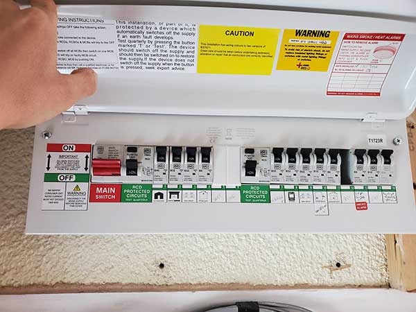
Split load consumer unit featuring 2 RCD’s
Consumer Unit With RCBO’s
This type of consumer unit layout has really emerged in recent years in response to the nuisance tripping addition to the wiring regulations. It essentially removes the use of RCD’s to create a split load board with RCBO’s (Residual Current Breaker with Over-Current) now taking their place.
Whereas an RCD protects against electric shock, earth faults and residual current, the RCBO protects against all of these plus overloads and short circuits, so essentially you get more protection for less and potentially less nuisance tripping if you suffer from such issues as you can do away with the RCD’s as the RCBO’s do a more complete job.
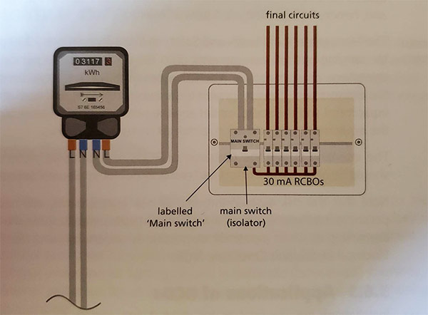
RCBO’s used in a consumer unit in place of RCD’s – Image courtesy of the BS7671 18th Edition Wiring Regulations
High Integrity Consumer Unit / Three-way Split Consumer Unit
This consumer unit, like the RCBO version was mainly born out the nuisance tripping addition to the wiring regulations and in effect combines the best features of each of the other types of configuration.
In effect what it does is splits the consumer unit into 3 sections. 2 of the sections are each protected by an RCD and in turn each of there individual circuits are protected by an MCB. These are then used for “less important” circuits such as upstairs sockets, cooker, electric shower or the similar, that don’t necessarily matter if they go off.
The third and final circuit(s) basically sit next to the main switch and are comprised of individual RCBO’s that provide all the protection for the circuit they are supplying. These circuits are considered highly important and as they are individually protected and outside of the RCD circuits, won’t trip with the other circuits protected under them.
These are generally reserved for items such as fire alarms, fire suppression, medical equipment and the such, where under no circumstances should they go off.
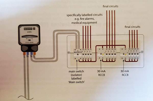
3-way circuit using RCBO’s and RCD’s – Image courtesy of the BS7671 18th Edition Wiring Regulations
What are RCD’s?
An RCD or Residual Current Device is a form of fuse that’s installed on a consumer or fuse board that provides full protection from electric shock, earth faults and residual current issues for the circuits or MCB’s installed beneath it.
In essence what it does is if it detects an imbalance in electrical flow or too much residual earth current, it will then cut the power to all of the MCB’s/circuits running under it, protecting them and any human presence from potential injury.
Aside from just being used in consumer units, RCD’s are available in many other forms such as built into plugs and sockets to protect otherwise unprotected circuits, built into certain appliances and many others.
When it comes to a modern split consumer unit, the use of RCDs is necessary for 2 reasons to meet the wiring regulations.
The first of these is to protect any socket which may be reasonably expected to supply equipment outside the house such as strimmers, lawn mowers, hedge trimmers, pond pumps, sheds, lights etc.
This rule pretty much covers every single socket in the house so the ring main should be placed on the RCD protected side of the consumer unit.
The second condition applies to any circuits where an earth fault current is not sufficient to blow the fuse, or trip the switch in the designated time allowance stated in the regulations.
This generally applies to higher Amp rated appliances (showers, cookers etc.) but it should always be checked with an electrician as to which circuits need to be placed on the RCD side of the consumer unit.
It’s also important to understand that RCD’s have a test button which creates a simulated earth leak with a resistor, and it is usually recommended that they are tested once a month to ensure they are operating correctly.
An information label near the consumer unit explains this. The resistor passes more current than that required for tripping, and the duration of the test is not limited, so testing in this way does not provide proof that the unit is working to specification.
RCD’s can also be switched off manually and can take the place of the isolator switch in the consumer unit, if they break live and neutral.
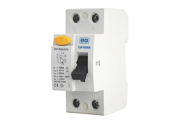
Standard consumer unit RCD
What are MCB’s?
An MCB or miniature circuit breaker is another form of protective device for circuits in a consumer unit. Working in the same manner as a fuse, if the device detects overload, short circuit or any form of overcurrent it quickly trips cutting the power and preventing potential fires or injuries.
Although used in most types of consumer unit setup, they are not required for those with RCBO’s as these do exactly the same job but with additional safety features.
In pretty much every other configuration they are a required feature for each and every individual circuit.
In days past when MCB’s became the protection device of choice for the consumer unit, the current rating for which a given MCB is designed to deal with have now been transferred into an international equivalent of our old imperial ratings.
This standard is called the Renard current rating and supercedes the imperial ratings as far as MCBs are concerned.
When it comes to matching an MCB to what is now the equivalent imperial rating, these are as follows:
- A 5 amp fuse can be replaced with a 6 amp MCB
- A 15 amp fuse becomes a 16 amp MCB
- A 20 amp fuse can be a 20 amp MCB
- A 30 amp fuse becomes a 32 amp MCB
- A 45 amp fuse must now be a 40 amp MCB
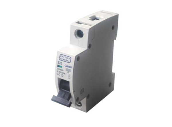
Standard 20A MCB for socket circuits
How is a Consumer Unit Wired up?
Now that you know exactly what elements make up a standard consumer unit and why they are needed it’s time to look at exactly how they are wired up and why this is done a particular way.
For this example we are going to keep things very simple and use a consumer unit with 1 main double pole isolations switch, 1 RCD and a couple of MCB’s just to show how they are connected. Essentially each MCB is wired up in the same way so can just be repeated.
Note: As you can see from the images, this is an old consumer unit and as such is still using the old wiring scheme e.g. red live, black neutral. For information on the new wiring colours and how they translate, see our new wire colours project here.
Obviously, when a consumer unit is being installed the power to your entire house is isolated so that everything can be connected up and tested before it put live for use!
Again, so that you know what’s what, here follows the key so you don’t have to keep scrolling up the page:
- A: Neutral terminal block for the main isolating switch side of the unit
- B: Neutral terminal block for RCD side of the unit
- C: Earth terminal block (takes both sides of unit)
- D: Main double pole isolating switch
- E: Generally 80 – 100 Amp RCD with 30mA (milliamp) sensitivity
- F: Neutral link cable from Main switch to terminal block
- G: Live feed from main switch to RCD
- H: Neutral link cable from main terminal block to RCD
- I: Neutral link cable from RCD to RCD neutral terminal block
- DIN Bar: the bar that holds each RCD and MCB in place
Step 1 – Test Circuits and Remove Old Fuse Box/Consumer Unit
One of the most important jobs your electrician will (or should) do before starting such a job is to first ensure they test all of the existing circuits in the property to make sure they function correctly and have no issues.
If this isn’t done then it can lead to all manner of issues when reconnecting and testing the circuits, so it’s best for both your electrician and also you to know if there are issues before any work is started.
Once all the testing has been completed the next job is to isolate the power to the existing fuse/circuit board and then remove it.
Again, it entirely depends on your existing electrical layout as to how this is done, but your electrician will certainly know.
Before any work is done, firstly it is ensured that power to the entire property is isolated so that the consumer unit can be safely worked on.
Once the old one is out of the way, the new one is fixed in place.
Step 2 – Add Main Double Pole Isolation Switch and RCD
When purchasing a consumer unit, it will either come with a main switch and RCD and possibly a number of MCB’s or it will come empty. Depending on how it’s being wired up and what your electrician has chosen to use will depend on what you go for.
If it comes empty, the necessary items are purchased and then installed as they are needed. Firstly, the double pole main switch is installed. Depending on what type of switch and board you have will depend on how this is done. Normally as it’s a required item it will be screwed on to a specific section of the board. Otherwise it’s clipped to the DIN bar with everything else.
The RCD is then clipped onto the DIN bar. The top clip is first clipped over the top of the bar and then bottom either clips over using a spring clip, a screw or simply just clips over.
The image below shows the mains double pole isolating switch in place on the DIN bar.
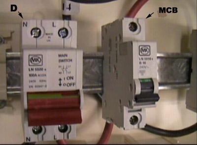
Consumer Unit with MCB and main double pole isolation switch
Step 3 – Connect up Main Switch and RCD
Once installed, the main switch is wired up. The 2 tails (or cables) coming from the meter are wired into the incoming section of the switch, normally the top. The Brown/Red live to the live terminal, the black/blue neutral to the neutral terminal.
Depending on the type of install will depend on what cables are used, you electrician will know exactly what to use. In this instance 16mm cables were used.
In the image below, this is shown as the live K and neutral J.
Next, the outgoing neutral F in the image below is wired into the neutral terminal block for the main switch side of the board and the live G is then wired to the incoming live of the RCD.
Finally, the incoming neutral of the RCD is wired to the main switch neutral block H and the outgoing neutral was then wired to the RCD neutral terminal block I.
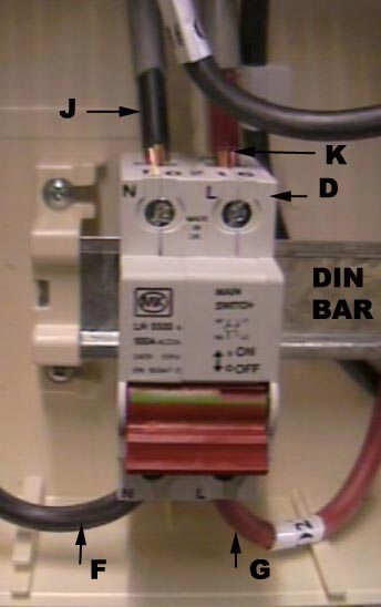
Main double pole isolation switch on din bar with live and neutral coming into the main double pole switch from the meter and earth terminal block
Note: As stated, it depends entirely on the type of board or consumer unit you have as to how it’s wired. A lot of more modern boards only have a single neutral block, so in this instance the live and neutral from the main switch are wired into the RCD as opposed to a neutral block first.
Step 4 – Add MCB’s
Once the safety side of the board is in place, the next items to be installed are the MCB’s, one for each required circuit.
Note: Depending on what the circuit will be running will depend on what size MCB is installed. Again, your electrician will know exactly what MCB can be used for a given circuit.
Firstly, MCB’s are clipped on to the DIN rail and positioned as required for the number of circuits that are being run from the consumer unit.
As the live power for each MCB comes from the RCD, a quick and simple method instead of wiring to the live of each MCB is to use a bus bar.
This simple copper bar features teeth that protrude up and run from the live input of the RCD to each MCB. When screwed tight this gives live feed to all the MCBs.
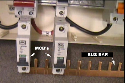
Consumer Unit with MCB’s and Bus Bar
Step 5 – Connect up MCB
Once the incoming live is connected using a bus bar for each MCB, the next job is to connect each circuit to it’s relevant MCB.
Ensuring the correct sized cable for the circuit you are connecting up is used (1, 1.5mm for lighting, 2.5mm for sockets etc.) it is stripped back as required (see our project on stripping cable for how this is done).
If this is a new consumer unit install for an existing property then your electrician will have either marked each circuit to identify what it powers or will work each one out as he gets to it.
The live O (either red/brown) is fixed into the top of an MCB on the RCD side of the unit, while the neutral M goes to the RCD neutral terminal block. The earth N*, which has been left unsheathed for clarity, goes into the earth terminal block C.
*: Any bare earth wires should be sheathed before they are installed using earth sheath, this is a legal requirement!
Once the first MCB is connected up, the others are connected in the same way, ensuring that each is connected to the correct size of MCB for the item(s) it’s powering.
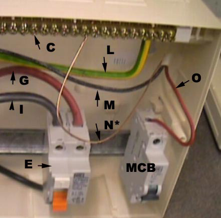
Circuit live connected to MCB with neutral going to RCD neutral terminal block
Step 6 – Connect Earth Cable From Meter
Once all of the MCB’s have been connected up, the final job then is to simply connect the earth running from the meter to the earth bar in the consumer unit
In the image above, this is shown as L and screws into the earth terminal block labeled C.
Step 7 – Test and Commission
The final stage left is then for your electrician to test every single circuit on the board and ensure it’s safe, wired correctly and has no issues what so ever.
This can be quite a lengthy process, but ultimately depends on how many circuits there are.
Once everything has been tested and confirmed safe, the consumer unit is then commissioned and the power turned back on.
Finally, the electrician then issues an EIC or DEIC (Electrical or Domestic Electrical Installation Certificate) certificate for all the work that has been carried out. Under Part P as replacing a consumer unit is notifiable works this is a legal requirement.
Wiring and connecting up a consumer unit is a major job and as it effects every single electrical item in your home, is certainly one that can only be done by a Part P registered electrician. However once completed it will ensure that your home and all of its electrical circuits are fully protected as are any of its residents.

